


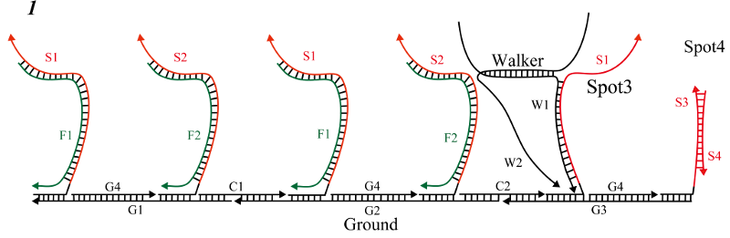
We designed a system to move the DNA origami structure via DNA Walker, as was previously described [1]. DNA Walker is a structure in which two DNA strands are partially hybridized, and each single strand represents a leg. In addition, the scaffolds are designed to form partial complementary sequences in a hairpin structure so that they do not bind, even if fuel DNA is added. However, as shown in Figure 1, when DNA Walker is used as a means for transporting a structure, there are two serious problem.
.gif)
First, S1 and S2 had exactly the same base sequence, and it is not known whether the DNA Walker reaction proceeds from the left foot or the right foot. The DNA Walker would be dangling when it moves forward from the right foot (w2), resulting in an undesired reaction system.
As a solution to this problem, we utilized mismatched base pairs. Specifically, we replaced a sequence with one that was not fully complementary to ensure that unintended chains did not bind to each other. When chains joined to form a double strand, since there were many complimentary combinations in each strand, they were combined, and the combination was intentionally reduced to make it uncoupled.
The principle of DNA Walker with a mismatched base pair is explained below. mismatched base pairs were incorporated into the base sequence to satisfy the specifications indicated in Table 1. The symbol ◯ indicates a successful combination, and the X symbol indicates that the components were not successfully combined. For example, S1 and F1 were coupled, whereas S1 and F2 were not.
| Strands | F1 | F2 |
|---|---|---|
| S1 | 〇 | × |
| S2 | × | 〇 |
Secondly, reaction speed needs to be considered. Even if the reaction proceeds from W1, Walker will be released if W2 is dissociated while W1 is dissociating and combining with Spot.
Therefore, we designed the reaction speed to be in the following order so as not to cause unintended reaction.
(1) Combining W1 and Spot1 (W2 and Spot2)
(2) Joining S1 and F1
(3) Joining S2 and F2
In order to make (1) the fastest among the three reactions, in (2), (3), a mismatched base pair was added near toehold so that the reaction became slower than (1). Also, regarding the reaction rate between (2) and (3), we changed the length of toehold by 1 so that (2) made the reaction faster than (3). Through these two points of design, we were able to design the reaction speed to be in the above order. With the above improvement, the problem of DNA Walker was solved. Next, briefly explain the movement of DNA Walker.
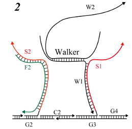
First, the left leg (W1) and right foot (W2) were combined in different arrangements; DNA Walker scaffolds were arranged in different steps, as described below, and the left leg (W1) and S1, followed by the right leg (W2) were designed. F1 and S1 combined to dissociate W1, and dissociated W1 and S2 then combined to move DNA Walker. The detailed reaction procedure is described in eight steps below.
In this process, we aimed to peel away S1 and W1 and float the left foot (W1).

- initial state
- S1 and F1 joined in the toehold region
- Binding progressed between S1 and F1
- In the chain substitution reaction of W1 and F1, W1 and F2 dissociated
- F1 and S1 were combined, and W1 was dangling
In this process, the goal was to combine Spot1 with the left foot lifted in step 1 in order to advance one step.

- Initial state
- Dangling W1 searched for complementary sequences
- W1 and Spot1 joined in the toehold region
- The binding of W1 and Spot 1 disrupted the hairpin structure, allowing DNA Walker to move one step
In this process, we aimed to peel away W2 and S2 and allow W2 to float.
- Initial state
- S2 and F2 joined in the toehold region
- Binding progressed between S2 and F2
- In the strand displacement reaction of S2 and F2, W2 dissociated
- F2 and S2 were combined, and W2 was dangling
In this process, the right foot (W2) that floated in step 3 was combined with Spot2, and the goal was to progress one step further.
- Initial state
- Dangling W2 searched for complementary sequences
- W2 and Spot2 joined in the toehold region
- The binding of W2 and Spot2 collapsed the hairpin structure. As a result, DNA Walker moved one step.
The subsequent step proceeded only when Fuel was not completely consumed; if the initial concentration of Fuel was low, the reaction would proceed until step 4.
In this process, we aimed to peel away S1 and W1 and float the left foot (W1).

- Initial state
- S1 and F1 joined in the toehold region
- In the chain substitution reaction between S1 and F1, F2 started to dissociate
- In the chain substitution reaction of W1 and F1, W1 and F2 dissociated
- F1 and S1 were combined, and W1 was dangling
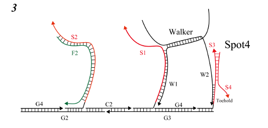
In this process, the goal was to combine Spot3 with the left foot lifted in step 5 in order to advance one step.
- Initial state
- Dangling W1 searches for complementary sequences
- W1 and Spot3 joined in the toehold region
- The binding of W1 and Spot3 collapsed the hairpin structure, allowing DNA Walker to move one step
In this process, we aimed to peel away W2 and S2 and allow W2 to float.
- Initial state
- S2 and F2 joined in the toehold region
- Binding progressed between S2 and F2
- In the strand displacement reaction of S2 and F2, W2 dissociated
- F2 and S2 were combined, and W2 was dangling
In this process, the right foot (W2) floated in step 7 was combined with Spot4, and the goal was to progress one step further.

-
Initial state
-
Dangling W2 searches for complementary sequences
-
W2 and Spot4 joined in the toehold region
-
By combining W2 and Spot4, Output was released, allowing DNA Walker to move one step.
